In my previous post and youtube video, I gave a brief introduction to LoRaWAN and also showed a circuit in which a small weather station is connected. The circuit can be operated at any location, even without an internet connection.
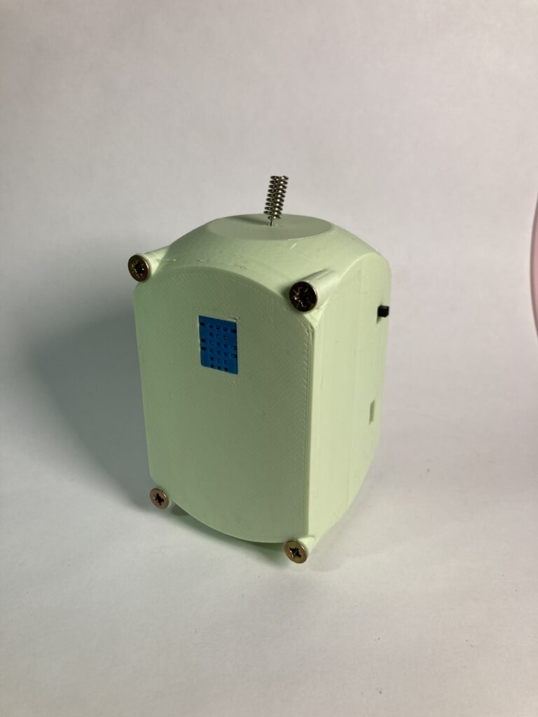
For this circuit, I have also built a suitable housing and written the software to operate the whole thing in a power-saving mode with batteries and LoRaWAN.
This is part one of a three-part series. In part 1, we dive into the fascinating world of hardware and circuits to create a working prototype. Part 2 is about getting the weather station software up and running and seeing the first data in the Helium Console. In part 3, we will develop a housing for the whole thing and display the data in a smart home dashboard.
Parts List
| Name | Quantity |
| SX1276 | 1 |
| Switch | 1 |
| DHT11 | 1 |
| AA Batteries | 3 |
| Battery pack | 1 |
| Arduino Nano-compatible Board | 1 |
| LoRa Antenna | 1 |
| Cables | Many |
SX1276
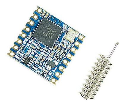
The LoRaWAN module I use here is very popular and is often used in commercial products as well. Handling the module is not easy. On the one hand, the pin connections do not comply with the standard on breadboards and must be expanded either via a PCB board or with soldered pins. On the other hand, handling the module in software is not the easiest thing either. I had to experiment a lot until I got it running on my Arduino. In the process, I spent countless hours testing.
Switch
Any electronic switch is sufficient. I have these lying around. I soldered pins so that I can use them on my breadboard. But also later, so that I can connect them to my weather station with jumper cables.
DHT11
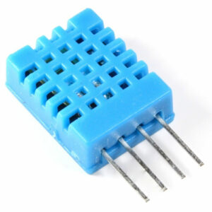
This is the temperature and humidity sensor. You can’t go wrong with this sensor. The disadvantage is that the temperature is a bit imprecise and only displays whole degrees. If you have higher requirements, you should choose a different temperature sensor.
Arduino Nano-Compatible Board
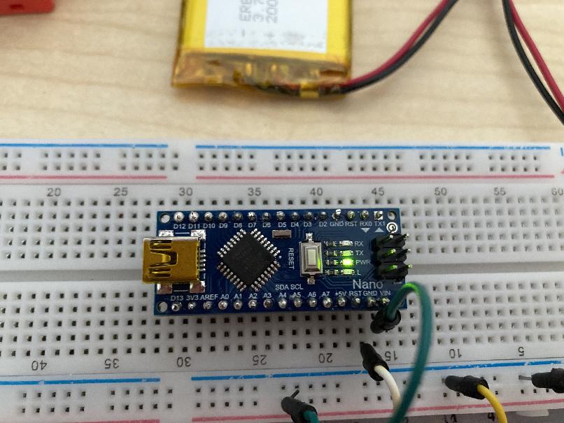
I used my Nano-compatible boards again. These can also be found here. The board is great, but during the course of the project, I discovered a few flaws in regards to software. This I will share in the next part.
Battery Pack (3x AA)
To power the weather station, batteries are used. Three AA batteries are connected in series via a battery pack to achieve a voltage of about 4.5 volts. Perfect for operating the weather station. I printed my battery pack myself. The design can be found here (file: flexbatterAAx3.stl).
Jumper Cables
I want to implement everything as a sustainable and reusable design. In case I ever think of improving or redesigning the weather station, I want to be able to reuse all parts. Therefore, I use jumper cables to ensure this. The weather station becomes a bit bigger than necessary, but it’s worth it to me.
LoRa Antenna (optional)
The LoRaWAN module comes with a small antenna. This is sufficient for prototypes. However, you will notice that the range is significantly limited with the supplied antenna.
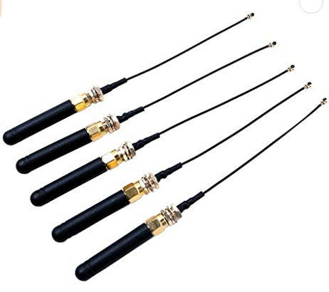
These small LoRa antennas are available on Amazon for about two euros per antenna. They may not be the best, but the range of the sensors increases with these antennas. I also purchased these for the later stages of the project.
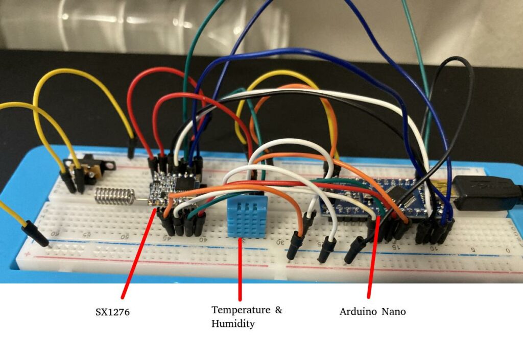
Circuit
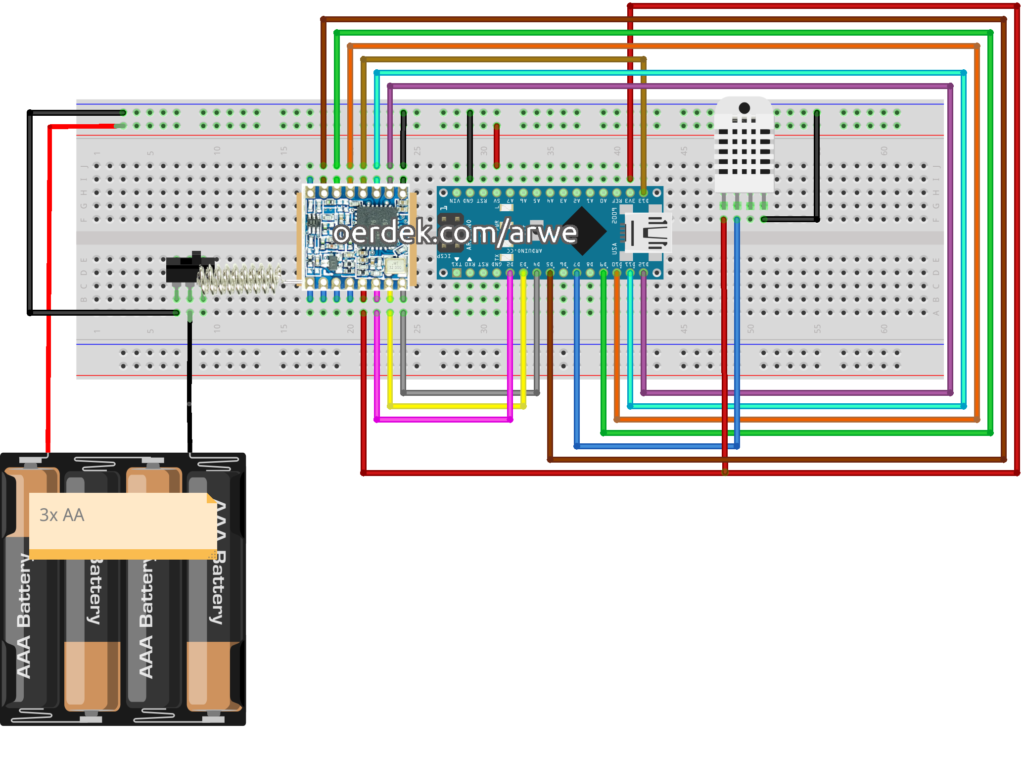
I designed my first digital circuit using a tool. Surprisingly, it turned out quite well, considering it was my first time. Here, you can see all the parts and how they need to be connected. The included mini-antenna is sufficient for the prototype.
LoRaWAN Network
For the use of LoRaWAN, I considered the Helium Network (“People’s Network”) and “The Things Network” (TTN). TTN was my first choice because the setup works quite well.
Just 500 meters away from my residence, there is a LoRaWAN gateway. Sending and receiving my first signals worked flawlessly. Unfortunately, the supplied antenna of my SX1276 seems to be too small. In contrast, the range of the Helium Network is outstanding. When registering on the Helium Console, you get free credits so you can start right away. In the further course, I will focus on the Helium Network.
Registration in the Helium Console
The Helium Console is the central interface when it comes to connecting sensors to the Helium Network. You set up your device, get keys, and can specify what happens to the data.
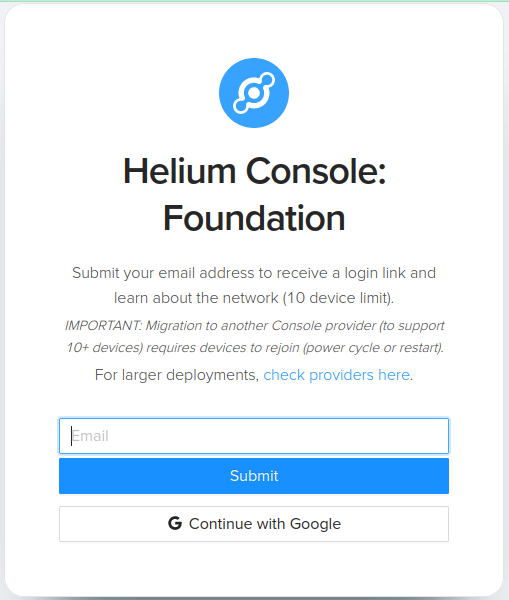
The Console is limited to 10 devices because it is not intended to use the Foundation’s Console for productive purposes. For larger use cases, there are providers that cover this.
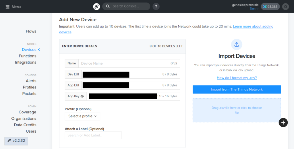
Creating a new device is nothing more than entering a name and saving the device. The important things for setting up the sensor are the Dev EUI, App EUI, and the App Key. With these three values, the Arduino can later establish a connection to the Helium Network and identify itself at hotspots.
Arduino Software
The Arduino library Beelan-LoRaWAN is a great library to get started with example code. The “send-class-A-OTAA” example file has almost everything pre-configured. The following must be adjusted.
1. Maintain access data: Enter the keys you saw earlier in the Helium Console here.
// OTAA credentials
const char *devEui = "0000000000000000";
const char *appEui = "0000000000000000";
const char *appKey = "00000000000000000000000000000000";
2. Maintain pin numbers: For our setup, we made the connections differently than in the example. Therefore, the pin numbers must be updated here. If you have connected your Arduino the same way as in my circuit, the following pin assignment should also work for you.
const sRFM_pins RFM_pins = {
  .CS = 10,
  .RST = 9,
  .DIO0 = 2,
  .DIO1 = 3,
  .DIO2 = 4,
  .DIO5 = 5,
};
Now you’re ready to go! Upload the program code and off you go.
Testing
To see if it really worked, you can check the Serial Monitor in the Arduino IDE. There, you will receive helpful messages about the state of the connection. In the Helium Console, you can now open the device and see the following content in the Event Log.
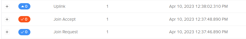
If you see a Join Request, Join Accept, and Uplink, the connection was successful! If only a Join Request is visible, your antenna is probably not strong enough. If nothing is visible here, please check if your circuit is connected correctly.
The example code sends a counter to the console. You can examine the content of the package by opening the details.
Result
We have now set up our circuit with the LoRaWAN module and Arduino, and sent our first signals to the Helium Network, which we can retrieve in the Helium Console. This marks a successful start to our project.
Next Steps
In Part 2 of this series, we will take a closer look at the software for the weather station, including the integration of the temperature and humidity sensor (DHT11) and how to send this data via LoRaWAN. We will also discuss the power-saving mode to maximize battery life.
In Part 3, we will create a suitable housing for our weather station and display the data in a smart home dashboard. This will allow us to access the collected data in a visually appealing and convenient way.
Overall, this project is a great way to dive into the world of LoRaWAN and learn how to build your own weather station. With each step, you will gain new insights and develop a deeper understanding of the technology behind it.